
Your shopping cart is empty! Please select the type which you want.
Home > Mall Dynamic > Function And Principle OF Bridge Rectifier
The electrical equipment used to convert alternating current (AC) to direct current (DC) is called a rectifier, and the rectifier is mainly divided into half wave rectifier (HWR) and full wave rectifier (FWR), where the full wave rectifier can be divided into center tapped full wave rectifier and bridge full wave rectifier.
Among them, bridge rectifier circuits are a common part of electronic power supplies, and many electronic circuits require rectified DC power supplies in order to power various electronic basic components from available AC power supplies. In daily life, such rectifiers can be found in various electronic AC power devices, such as motor controllers, modulation processes, welding applications, etc. In this article, we will introduce what is a rectifier and how it works
A bridge rectifier is an alternating current (AC) to direct current (DC) converter that rectifiers the main AC input into a DC output. Bridge rectifiers are widely used in power supplies that provide the necessary DC voltage for electronic components or devices. They can consist of four or more diodes or any other controlled solid-state switch. According to the load current requirements, the appropriate bridge rectifier should be selected. Component ratings and specifications, breakdown voltage, temperature range, transient current ratings, forward current ratings, installation requirements, and other factors to be considered are considered when selecting a rectifier power supply for the appropriate electronic circuit application.
The structure of the bridge rectifier is shown in the figure below. The circuit can be designed with four diodes, namely D1, D2, D3 and D4, and a load resistor (RL). The connection of these diodes can be done in closed-loop mode to efficiently convert AC to DC. The main advantage of this design is that there is no dedicated center-tapped transformer, so the size and cost are lower.
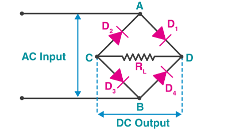
Once the input signal is applied to the two terminals (such as A and B), a 0/D DC signal can be obtained on the RL. The load positive is connected between terminals C and D. The two tubes are arranged in such a way that the current is conducted by the two diodes every half cycle. Diode pairs like D1 and D3 will conduct current throughout the positive half cycle. Similarly, D2 and D4 diodes will conduct current throughout the negative half cycle.
The main advantage of a bridge rectifier is that it produces almost twice as much output voltage as a full-wave rectifier using a center-tapped transformer. But the circuit does not require a center-tapped transformer so it is similar to a low-cost rectifier. The circuit diagram consists of various stages of equipment such as transformers, diode Bridges, filters and regulators. Typically, a combination of all these blocks, called a regulated DC power supply, powers a variety of electronic devices.
The first stage of the circuit is a step-down transformer that changes the amplitude of the input voltage. Most electronics projects use a 230/12V transformer to step-down the 230V AC supply to 12\ AC.
The second stage is a diode bridge rectifier, which uses four or more diodes depending on the type of bridge rectifier. Selecting a specific diode or any other switchgear for the corresponding rectifier requires consideration of a number of devices such as peak reverse voltage (PIV), forward current lf, rated voltage, etc. It is responsible for generating a unidirectional or direct current at the load by conducting a set of diodes for each half cycle of the input signal.
Because the output after the diode bridge rectifier has a pulsating nature, and in order to produce it as pure DC, it must be filtered. Filtering is usually performed by connecting one or more capacitors at both ends of the load, as shown in the figure below, where smoothing of the wave is performed. The capacitance rating also depends on the output voltage.

In addition, the final stage of the regulated DC power supply is a voltage regulator that keeps the output voltage at a constant level. Assume that the microcontroller operates at 5V DC, but after bridge rectification
The output is about 16V, so to reduce this voltage and maintain a constant level (regardless of how the voltage on the input side varies), this requires a regulator.
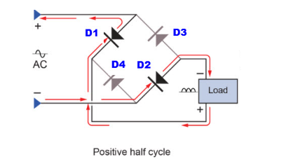
As mentioned above, the single-phase bridge rectifier consists of four diodes, and this configuration straddles the load. In order to understand the working principle of the bridge rectifier, the following circuit must be considered for illustration.
During the positive half cycle of the input AC waveform diode, D1 and D2 are forward biased and D3 and D4 are reverse biased. When the voltage exceeds the threshold level of diodes D1 and D2, the on-load current begins to flow through it, as shown by the path of the red line in the figure below:
During the negative half cycle of the input AC waveform, Diodes D3 and D4 are forward biased, D1 and D2 are reverse biased. As is shown in the picture below, When these diodes start to switch on, the load current Start flowing through D3 and D4 diodes.

It can be observed from above that in both cases the direction of the load current is the same, i.e. from top to bottom as shown in the figure - so it is one-way, that is, direct current. Thus, by using a bridge rectifier, the input AC current is converted to DC current. The load output of this type of bridge wave rectifier is pulsating in nature, but producing pure DC requires an additional filter, such as a capacitor. The same operation applies to different bridge rectifiers, but in the case of controlled rectifiers, thyristor triggering is necessary to drive the current to the load.
Bridge rectifiers are divided into several types according to different factors: power supply type, control capability, bridge circuit configuration, etc. Bridge rectifiers are mainly divided into single-phase and three-phase rectifiers. These two types are further divided into non-controlled, semi-controlled and fully controlled rectifiers. Some of these types of rectifiers are described below.
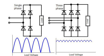
The nature of the power supply, that is, single-phase or three-phase power, the source determines these rectifiers. Single-phase bridge rectifiers consist of four diodes that convert AC to DC with a stem, while three-phase rectifiers use six diodes, as shown below. Depending on circuit elements such as diodes and thyristors, these rectifiers can also be uncontrolled or controlled rectifiers.
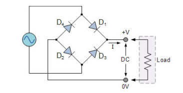
The bridge rectifier uses a diode to rectify the input. Since the diode is a one-way device, the current is only allowed to flow in one direction. With this diode configuration in the rectifier, it does not allow the power to vary according to the load requirements. So this type of rectifier is used for a constant or fixed power supply, as shown below:
In this type of rectifier, AC/DC converters or rectifiers - instead of uncontrolled diodes, use controlled solid-state devices (such as SCRS, MOSFETs, IGBTs, etc.) to vary the output power at different voltages. By triggering these devices at different times, the output power of the load is appropriately changed, as shown in the figure below:

Due to their low cost compared to center taps, they are widely used in power circuits.
This can be used to detect the amplitude of a modulated radio signal.
Bridge rectifiers can be used to provide polarization voltage in welding.
Alternating current can be converted into direct current
Regulated DC power supply
The advantages of bridge rectifier include the following:
The rectifier efficiency of full wave rectifier is twice that of half wave rectifier.
In the case of full-wave rectifiers, higher output voltage, higher output power and higher transformer utilization. The ripple current is low and the frequency is high, so a simple filter circuit is needed for full wave rectification. The transformer secondary does not require a center tap, so in the case of a bridge rectifier, the required transformer is simpler. If there is no need to boost or buck the transformer can even be omitted.
For a given power output, a smaller size power transformer can be used in the case of a bridge rectifier because the current in both the primary and secondary windings of the power transformer flows through the entire AC cycle.
High frequency and low ripple voltages are achieved with a simple filter circuit.
Compared to center-tapped rectifiers, bridge full-wave rectifiers are more efficient:
No center-tapped transformer required
The disadvantages of bridge rectifier include the following:
Using two additional diodes results in an additional voltage drop, which reduces the output voltage.
Four diodes are required, so the cost of the rectifier will be high.
Once rectification of a small voltage is required, the circuit is not suitable because the two diodes can be connected in series and provide double voltage due to their internal resistance
Descend.
These circuits are very complex to design.
Compared with the center tapped rectifier, the power loss of bridge rectifier is greater
Compared to other rectifiers, bridge rectifiers are the most efficient type of rectifier circuit. This is a full-wave rectifier, which, as the name suggests, uses four diodes connected in a bridging form. So this type of rectifier is called a bridge rectifier,
It should be noted that in the bridge rectifier, four diodes are used to design the circuit, and full wave rectification can be achieved without the use of a center-tapped transformer. The rectifier is primarily used to provide full-wave rectification in most applications, while the arrangement of four diodes can be done in a closed-loop arrangement to efficiently change AC to DC. The main benefit of this arrangement is that there is no center-tapped transformer, so size and cost will be reduced.
Mall Dynamic
